Previous part:
1. Introduction & overview
2. Reading data form a ‘dumb’ thermostat and various temperature sensors (Arduino)
2.1 Reading a normal thermostat (understanding how a thermostat works part I)
To understand what a thermostat is supposed to do I wanted to measure when my regular thermostat would turn the furnace on and off. Of course, I could have done research on how a thermostat works, but because this is mostly a learning project I took a more data-collecting approach. In addition, doing research was difficult because I did not know what to look for or what search terms to use. However, I did know that our boiler was not a new model using the more advanced OpenTerm protocol, but was using the simple on/off system. The on/off system is based on 24V and two wires going in and out of the boiler in which the thermostat simply allows or does not allow current to go through the wire.
The XBee and LCD part of the Arduino was relatively easy to setup, following Robert Faludi’s example of his twitter reader. Reading when the thermostat would turn the boiler on and of was more difficult however. I had expected the thermostat to control the boiler using a direct current and that it would simply open or close the circuit between the boiler and thermostat. When I measured the voltage using a multimeter I did not get a reading. Switching to alternating current gave me a nice 24 Volt reading. I also noticed that the voltage stayed the same regardless of whether the thermostat was sending the boiler to an on or off state. In measuring the internal resistance of the thermostat, there was a big difference between the on and off state. The thermostat does not actually close to circuit in the off state, but instead increases its resistance and as a result decreases the amount of current going through the circuit to and from the boiler. I assume this is because I have an electronic thermostat that gets its power from the furnace. In the off mode it gets enough power from the boiler to keep itself alive, but not actually turn the boiler on.
2.2 measuring current with an Arduino
Measuring a difference in current in an AC circuit is unfortunately more difficult with an Arduino. An Arduino can only measure DC Volts. Trying out various options, including relays and diode rectifiers I ended up with the following setup. The basis is the AC circuit going to and from the boiler also turning on a LED when it sends the ON signal to the boiler. A photoresitor sitting next to the LED is connected to the Arduino. Both LED and photoresistor are covered with a LEGO DUPLO block (figure 4). Whether the thermostat turns the boiler on or off is measured by the difference in light intensity reaching the photoresistor. A red LED and a red DUPLO block gave the best results. To prevent the LED from flickering, a diode bridge and a condensator are used to rectify the current as much as possible. The schematic for measuring the boiler state from my normal thermostat is shown in figure 3. The Arduino code to read the photoresistor is explained in paragraph 2.6.
The data collected from the photocell is shown in figure 5. Here the on and off states are clearly shown in the top graph where every low value means the boiler was turned on (six times per hour). The top graph represents the number of volts measured by the Arduino. A drop in the amount of volts actually means an increase in light intensity showing the LED is on. The only downside is that my daughter wanted her DUPLO back as soon as she saw that I had commandeered one for my own use. For now she is letting me use it.

Figure 3: schematic reading current from a AC circuit
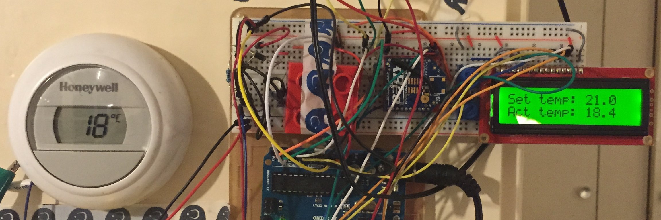
Figure 4: using LEGO DUPLO and washi tape with an Arduino
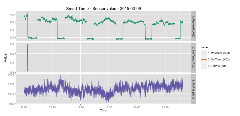
Figure 5: sensor values: boiler state, set temperature and actual temperature
2.3 Inaccurate TMP36 temperature sensor
For the temperature sensor I started with the TMP36 temperature sensor, included in both the Arduino and the BWSN starker kit. This sensor however is highly inaccurate. As shown in the bottom graph of figure 5. The bottom graph shows the temperature in Celsius * 100. Not only do the temperature readings highly fluctuate, there also seems to be little to no correlation between the boiler heating up the house and the temperature readings by the sensor. This, as on can imagine, problematic when building a thermostat.
2.4. Other temperature sensors & improved temperature readings
In order to improve the temperature readings I made a couple of improvements. First, I moved the sensor further from the electronics to prevent measuring any heat caused by the Arduino or the XBee. Second, I tried different temperature sensors. I bought two thermistors: a thermistor in a stainless steel enclosure (figure 7), and a precision thermistor (TS-NTC-104). Third, I connected all sensors to the 3.3V power output of the Arduino and connected the VREF port of the Arduino to the powerline of the sensors. This resulted in much better readings as shown in figure 6. The best results where shown by the thermistor in the enclosure, most likely because the longer wire of this sensor allowed me to put it away from direct sunlight.
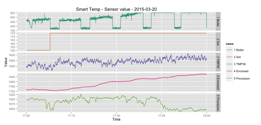
Figure 6: Improved temperature readings
In addition to the thermistors I also bought a digital temperature sensor. The response time of this sensor was not fast enough for the use described in part 3. The set temperature is a simple potentiometer where the voltage readings of the Arduino are converted to a temperature scale with a range of 10 to 30 degrees Celsius, rounded to half a degree.
2.5 Final breadboard layout and schematic
The final breadboard layout and schematic for this first fase of the project are shown in figure 8 and 9 below.
2.6 Arduino code for reading sensor data
The Arduino code for reading the voltage of the photocell (boiler state), set temperature potentiometer and the TMP36 temperature sensor all use the same code. All three use the ARDX example of reading an analogue value of the TMP36 temperature sensors http://oomlout.com/a/products/ardx/circ-10/ . Shown in the code snippet below is the getVoltage() function that reads the analoge value.
For the thermistors, I largely followed the great tutorial from Adafruit about using a Thermistor https://learn.adafruit.com/thermistor/using-a-thermistor but created to handle a different a B-coefficient and resistance at room temperature for each thermistor. As shown below with the thermistorRead() function below.
The complete Arduino sketch for this project can be found on github https://github.com/niektemme/smarttherm-arduino/
This file contains hidden or bidirectional Unicode text that may be interpreted or compiled differently than what appears below. To review, open the file in an editor that reveals hidden Unicode characters.
Learn more about bidirectional Unicode characters
| //code snippet from: https://github.com/niektemme/smarttherm-arduino/blob/master/arduino-sketch/smarttherm.ino | |
| //ref voltage | |
| #define aref_voltage 3.3 | |
| //variables for settemp variable resistor | |
| int sensorPin = 0; //sensor = settemp | |
| int sensorValue = 0; | |
| int sensorOldValue = 0; | |
| //variables for TMP36 | |
| int temperaturePin = 1; //act temp | |
| int tempValue = 0; | |
| int tempOldValue = 0; | |
| int tempDisValue = 0; | |
| int tempDisOldValue = 0; | |
| //variables for boiler on off sensor (photo resistor) | |
| int boilerPin = 2; | |
| int boilerValue = 0; | |
| //variables for thermistor | |
| int thermistorPin= 3; | |
| int thermistorValue =0; | |
| int thermistor2Pin= 4; | |
| int thermistor2Value =0; | |
| … | |
| void setup() { | |
| analogReference(EXTERNAL); //analogue refference | |
| … | |
| } | |
| void loop() { | |
| … | |
| float temperature = tempReading(temperaturePin); //getting the voltage reading from the temperature sensor | |
| temperature = (temperature – .5) * 100; //converting from 10 mv per degree wit 500 mV offset | |
| //to degrees ((volatge – 500mV) times 100) | |
| tempValue = (int) (temperature*100); | |
| //reading boiler on of state | |
| float boiler = getVoltage(boilerPin); | |
| boilerValue = (int) (boiler*100); | |
| //avaraging set temperature to .5 degrees celcius | |
| float sensorCalcValue = (round(((analogRead(sensorPin)/5.0)+100.0)/10.0*2.0))/2.0*10.0; | |
| sensorValue = (int) sensorCalcValue; | |
| //Reading thermistor 1 value using thermistorRead() function, sending nominal value and bcofficient (steinhart) to function | |
| float thermistor = thermistorRead(thermistorPin,10000,10000,25,3950); | |
| thermistorValue = (int) (thermistor*100); | |
| //Reading thermistor 2 value using thermistorRead() function, sending nominal value and bcofficient (steinhart) to function | |
| float thermistor2 = thermistorRead(thermistor2Pin,100000,100000,25,4261); | |
| thermistor2Value = (int) (thermistor2*100); | |
| … | |
| } | |
| //function to get analoge value to digital range | |
| float getVoltage(int pin){ | |
| return (analogRead(pin) * .004882814); //converting from a 0 to 1023 digital range | |
| // to 0 to 5 volts (each 1 reading equals ~ 5 millivolts | |
| } | |
| //tmp36 sensor fucntion | |
| float tempReading(int pin){ | |
| int tempRead = analogRead(pin); | |
| float voltage = tempRead * aref_voltage; | |
| voltage /= 1024.0; | |
| return voltage; | |
| } | |
| //function for read thermistor value given nominal value and bcofficient (steinhart) | |
| float thermistorRead(int pin, int seriesr, int thermistnominal,int tempnom, int bcof) { | |
| float tempRead = analogRead(pin); | |
| // convert the value to resistance | |
| tempRead = 1023 / tempRead – 1; | |
| tempRead = seriesr / tempRead; | |
| float steinhart; | |
| steinhart = tempRead / thermistnominal; // (R/Ro) | |
| steinhart = log(steinhart); // ln(R/Ro) | |
| steinhart /= bcof; // 1/B * ln(R/Ro) | |
| steinhart += 1.0 / (tempnom + 273.15); // + (1/To) | |
| steinhart = 1.0 / steinhart; // Invert | |
| steinhart -= 273.15; // convert to C | |
| return steinhart; | |
| } |

Figure 7: Enclosed thermistor MJSTS-103-3950-1-600-3D

Figure 8: Final breadboard layout project part 1

Figure 9: Final schematic project part 1
Next part:
3. Sending data, at 1,000 values per second, to a Raspberry PI (Python)

Reblogged this on Dinesh Ram Kali..
Pingback: Enabling technologies: how to build your own NEST | SmartDomus